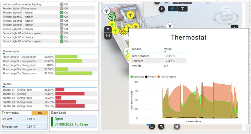
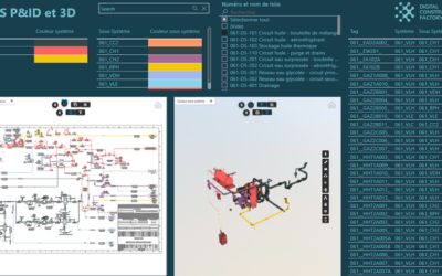
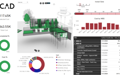
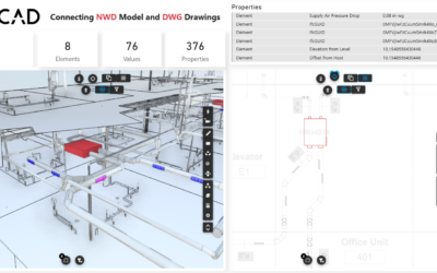
This article is part of a series of publications that focus on the use of Vcad and other platforms such as Microsoft Fabric and Azure in managing IoT processes and creating BI dashboards based on real-time data.
REAL-TIME IOT DATA, MICROSOFT FABRIC AND VCAD
REAL-TIME IOT DATA, MICROSOFT FABRIC AND VCAD #2
REAL-TIME IOT DATA, MICROSOFT FABRIC AND VCAD #4
REAL-TIME IOT DATA, MICROSOFT FABRIC AND VCAD #5
REAL-TIME IOT DATA, MICROSOFT FABRIC AND VCAD #6
The first article in the series is an overview of the platforms involved and the technologies used and how, when integrated together, they can represent a complete Iot real-time management system.
The second article describes the phases into which the Iot management system can be divided, highlighting the processes of Digital Twin creation and device simulation.
Intro
In this article we will examine in detail the benefits of using the BIM model as a guiding tool for defining IoT devices, performing congruity checks, and preparing the configurations and real time data needed to create dashboards to monitor and manage the data generated by sensors and connected devices.
The diagram below summarizes the key processes and interactions between the platforms:
- Bim model data extraction through Vcad.
- Definition of device types through a configuration file.
- Identification of the elements of interest present in the Bim model and mapping with a configuration file using Fabric-Power BI data transformation engine.
- Creation of a data structure that allows the creation of IoT instances (via Azure DPS).
- Reading the data in real-time from Azure IoT Hub.
- Creating the data structures necessary to create real-time reports by mapping real-time data to the device definition and definition file.
In a later article we will describe in detail how, once the database is created, it will be possible to build Power BI reports capable of displaying the sensor data in real time, customizing them through the use of colors, themes and icons, locating them directly in the model through the use of the Vcad custom visual.
It is important to note that the steps we are describing depend on the file format you use, the information the file contains, the type of report you want to make, etc. Therefore, it is not possible to define an approach that is valid in all scenarios. In any case, however, we can define steps and guidelines that, thanks to the use of Vcad, are a reference in the implementation of projects like this one.
The following is a brief description of the architecture.
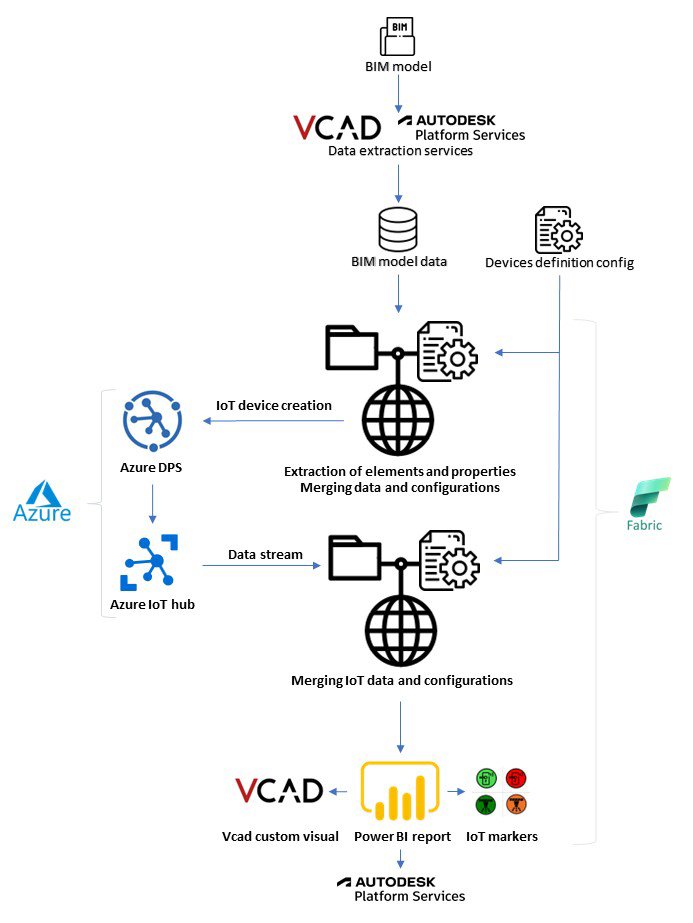
The various processes will be described in detail below.
Extraction of Bim model data using Vcad and identification of elements of interest
The extraction of the data contained in the Bim model through the use of the Vcad service will allow the query, identification and extraction of the information that will form the basis needed for the subsequent data transformation operations necessary for both the creation of Iot devices and the construction of reports.
Without going into details regarding the data extracted from the various types of models (IFC,RVT,Navisworks), we can say that each element in the model is defined in a data structure (called ‘Assets’ in Vcad) that contains the name, type and an ID that acts as a link to the geometries of the model. Linked to this structure is another structure (‘Properties’) which, as the name implies, contains an arbitrary number of attributes that belong to the Asset.
In this structure, we can find a lot of information that will be useful in the definition of the device and Digital Twin, such as the unique identification code of the asset, its location in the space (e.g., building, floor, room) or the relationship with other elements of the model.
In this article, we will focus on two types of elements that we want to manage:
Lighting Fixtures
Lighting Fixures Dimmable
Starting from the data extracted in Vcad, using simple data transformations in Power BI, we will be able to isolate the elements of type Lighting_Fixtures.
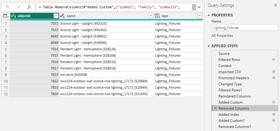
Similarly, we will proceed to define the structure that will group the devices of type Lighting_Fixture_Dimmerable.
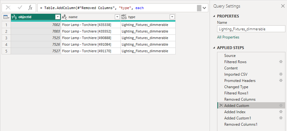
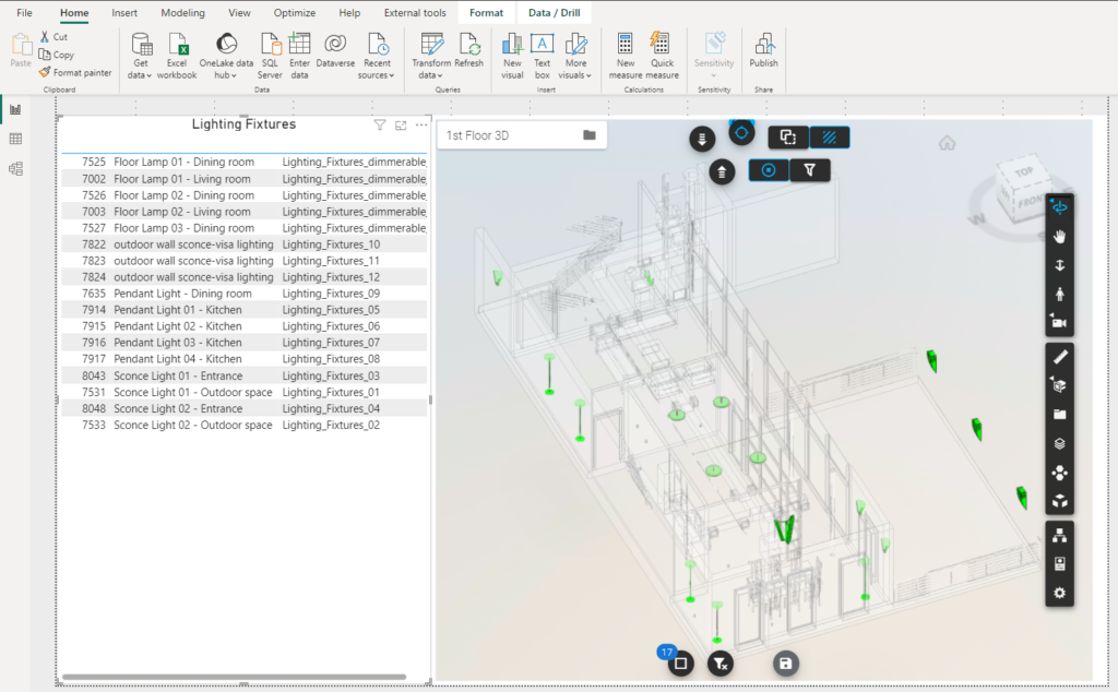
Already at this early stage, the advantages of having a Bim data to guide the definition of the devices is evident. In addition, Vcad offers us the possibility to display the selected data directly in the Bim model in the Power BI context.
The image below shows a simple report page containing the table with the extracted information and its highlighting in the Vcad custom visual.
Definition of device types through a configuration file
A key step in the procedure is to create a file to define the properties of the devices that will make up our project. An example of configuration can be represented by the following structure.

DeviceType, represents the key that defines the device type and binds the configuration to the structures previously identified and extracted from the model.
SensorName, identifies the type of sensor that will be part of the device. Note that a single device may have two values like in the example of Lighting_Fixtures_Dimmerable which will have Switch and Dimmer.
DeviceTypeSensorName, creates a unique key for Device Type and SensorName.
The other elements will be described later in the real-time data section.
Creating the data structure for creating IoT instances
We can now create a table that fully defines the individual device instances in the Bim model. An example of a structure might be as follows.

The table contains all the information of the instances of the devices identified in the model.
For example, IdDevice represents the unique device code (in our example a simple progressive), objectId is the link to the geometry.
Interestingly, the number and name of the room where the devices are located were extracted by the Vcad service directly from the BIM model. This information can be used both to perform congruity checks and to group devices according to the rooms.
By applying further transformations, it will be possible to use the table to create device instances, such as on Azure DPS (procedure described in the previous article).
Reading data in real-time from Azure IoT Hub
The instance table can be used to set up the data needed for real-time visualization of data from sensors.
In our example, the real-time sensor data comes from an Azure Iot Hub and is sent to Power BI using Fabric Synapse Real-Time Analytics as described in the first article.
To connect to the real-time data simply use the data source in DirectQuery.
(https://learn.microsoft.com/en-us/azure/data-explorer/power-bi-data-connector?tabs=web-ui)

The key that will bind the real-time data to the model instance table and configurations will be the IdDeviceMeasure field.
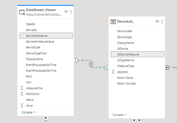
The IdDeviceMeasure field will then allow us to retrieve related instances in the BIM model and the ability to view their respective data and geometries.

Instead, the DeviceType field allows us to connect to the configuration structure and retrieve the information needed to display the data in the Vcad viewer and reports. Examples of configuration data are:
- Measure Unit, Min Value, Max Value: for setting up tables and graphs.
- Viewer Default, in the case of devices with more than one sensor, indicates what the default sensor used to connect to the Vcad viewer should be.
Another information that could be retrieved from the configuration file, is the icon associated with the sensor. In our example, however, the icon definition logic is implemented on the Kusto DB side because the value (state) of the sensor is also taken into account and it is convenient to get it as streaming data.
Conclusions
As we had a chance to see in the article, it is possible to manage some fundamental steps of an IoT project without resorting to specific platforms or writing ad hoc code. The use of Vcad to extract data from BIM models, the possibility offered by Microsoft Fabric to import data even in real-time, allows us to quickly and easily implement a solid dataset.
Many processes can start from this dataset, helping us to create reports and dashboards to manage and share IoT data more easily and cost-effectively.

